 EU | en
Blog Post
Vapor Recovery and Overfill Protection in the Tank Truck Market
Nov. 24, 2021
The U.S. 1970 Clean Air Act (CAA), amended in 1977 and 1990, legislated major reductions of atmospheric hydrocarbon pollution. Studies have shown that up to 95% of emissions from the transportation of petroleum could be contained for recycling. As a result, the petroleum industry began to seriously examine gasoline vapor emissions and controls. Although attempts have been made to develop top-loading vapor recovery systems, the advent of bottom-loading provided superior vapor recovery technology. Today, bottom-loading vapor recovery technology dominates and has been applied worldwide.
Vapor recovery involves the prevention of gasoline vapors escaping to the atmosphere during the loading and unloading process. This is called stage 1 vapor recovery. It requires that vapors be collected from underground service station tanks and transported to the terminal for processing. The introduction of stage 1 vapor recovery requires modifications to the service station, tank trailer, and terminal equipment. Modifications include a separate vapor transfer port to the underground tank. This two-point vapor recovery system requires both a vapor and a fill port. A single-point vapor recovery system uses the drop piping to transport using a special coaxial elbow. Two-point systems are preferable due to faster unloading.
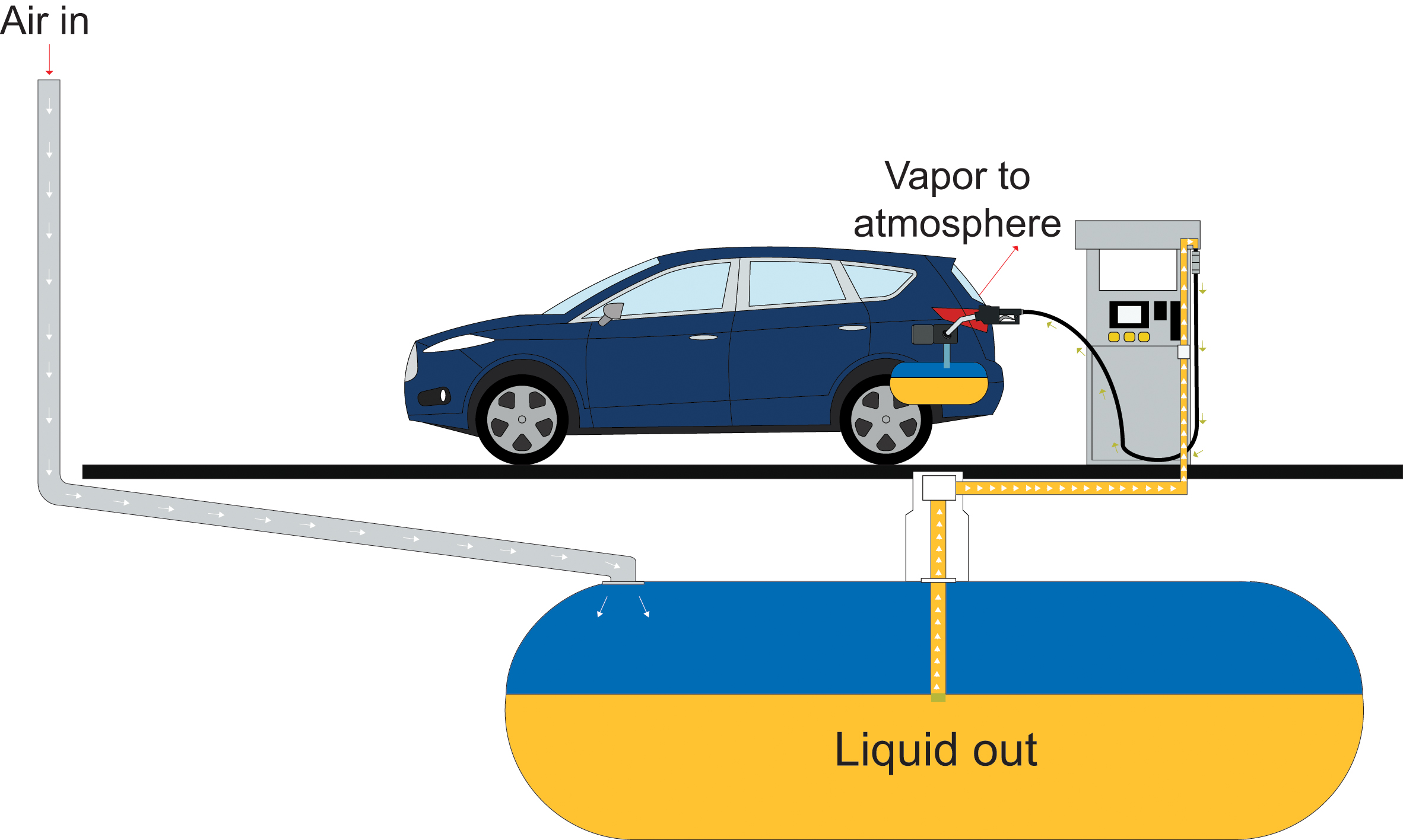
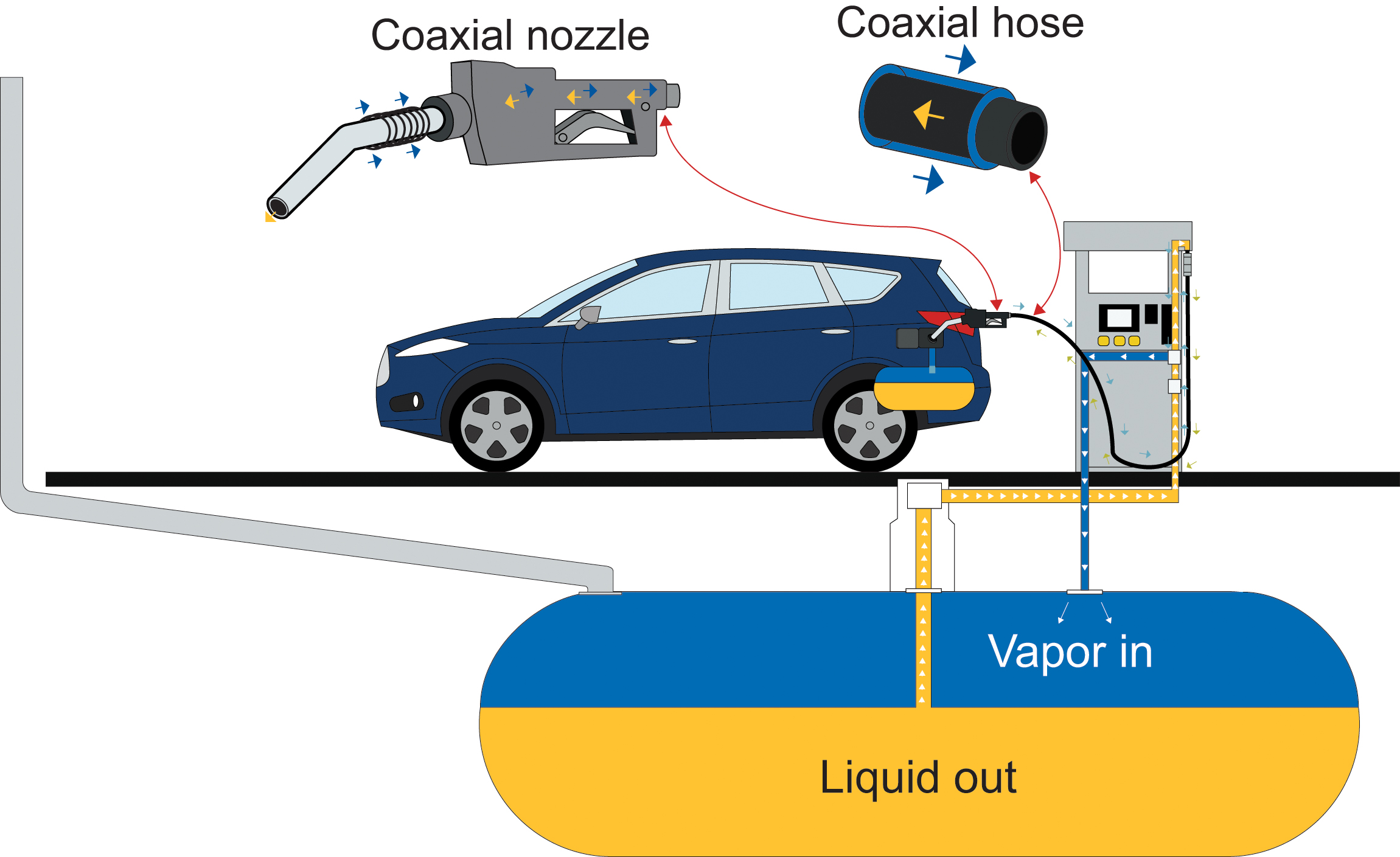
Stage 2 vapor recovery involves the prevention of automobile tank vapors from escaping using special nozzles and additional modifications to service stations. This post will deal only with stage 1 vapor recovery; however, several illustrations of stage 2 vapor recovery are provided below.
Overfill Protection
Overfill protection has evolved and become more complex over the years, especially with the adoption of sealed transportation systems that do not allow for visual inspection. Bottom-loading and vapor recovery applications are two examples of sealed systems. As automation increased, so too did the danger of overfilling compartments. This can occur when:
- Incorrect information is given to the pump/metering device at the terminal
- There is a failure of the pump/metering device
- Operators attempt to fill an already full compartment
- Tankers return to the terminal with an undelivered partial load
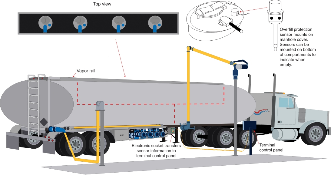
Early mechanical overfill protection systems, such as floating ball cut-off devices and pneumatic Venturi cut-offs, could not easily be checked and were found inconsistent. Today the only reliable and verifiable performing equipment is electronic monitoring systems. These electronic overfill protection systems work in conjunction with terminal equipment to serve as a secondary shut-off mechanism should the terminal loading equipment fail, or when operator error results in an overfill situation. Electronic overfill systems typically consist of:
- An electronic sensor is located at the interior top of each compartment usually mounted on manhole covers. The sensor signals if it is wet or dry.
- Bottom sensors, which are sometimes installed to check if the compartment is empty.
- An electronic socket on the bottom exterior of the tanker, which is electronically connected to each sensor. The socket includes physical grounding.
- Dixon's rack monitor (part number FT7000) at the terminal loading rack, which is connected by cable to the tanker socket. The monitor continuously checks each sensor to permit the pumping of petroleum. If a sensor becomes wet, the signal is interrupted and immediately shuts down the rack pumping equipment. A shut-off signal can result from the top sensor changing from a dry to a wet signal signifying the compartment is overfilled. At the terminal, if the bottom sensor is wet (signifying a compartment is not empty), loading will be prevented.

Vapor Processing at the Terminal
Petroleum vapors collected at the terminal are typically processed through large reactors filled with activated carbon. The activated carbon acts as a filter, trapping the hydrocarbon molecules. When saturated, the molecules are drawn off the carbon by vacuum, and the resulting product is condensed and reintroduced to the gasoline manufacturing process. There are typically two reactors. As one reactor is collecting the hydrocarbons, the other is under vacuum, discharging the vapor by product.
In some locations, gasoline vapors are collected but not processed. They are simply burned (flared) into the atmosphere.
Bottom-Loading and Vapor Recovery Equipment
Manholes and Accessories
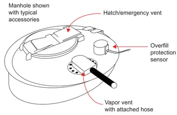
Manholes provide personnel entry to the petroleum tanker compartment. Manholes typically come in diameters of 16" and 20". They consist of a ring welded to the top of the compartment onto which the manhole cover is mounted. The cover is typically manufactured with mounting locations for ancillary items, such as an inspection hatch, vapor vents, and overfill protection sensors.
There are several accessories that can be mounted on manholes. The most important is the emergency vent, which is designed as a surge suppression relief valve. It will open in case of an emergency, such as the overfilling of the compartment (preventing excessive pressure buildup), or for pressure relief in case of a fire, which can cause tanker pressure buildup. These vents open when pressure exceeds approximately 3.6 PSI. This 10" vent is also a hatch, which can be manually opened for filling the compartment or for inspections. The emergency surge vent is a mandatory requirement for DOT 406 petroleum tank trucks and has a very high venting capacity.
Another required accessory is a normal or pressure vacuum (PV) vent, which is usually thread mounted and protrudes to the underside of the cover. This small, limited capacity vent compensates for ambient-temperature-generated pressure or vacuum buildups. This in-and-out breathing vent moderates compartment conditions close to exterior atmospheric pressures.
Other accessories mounted on manhole covers can include a vapor vent (shown below) and an overfill protection sensor.
Vapor Vents
Vapor vents are required to allow air/vapor into or out of the compartment during loading and unloading. They prevent a vacuum or pressure buildup in the compartment and allow for smooth and rapid filling or unloading.
Today, vapor vents are generally mounted onto the manhole and are pneumatically operated.
Pneumatic manhole mounted vents are popular because they can be controlled by air valves and are normally operated with the emergency valve by a pneumatic control box on the tanker. The operator simply pulls the control knob for the required compartment. Pneumatic vents can also have a built-in sequencing feature to verify all vents are open prior to loading.
Tank trucks equipped for vapor recovery will have the vapor vent adapter connected to the vapor piping systems using a short length of hose. Some mechanical vents may need special hoods (metal or rubber) with spouts to connect to the vapor plumbing.
 Sequential vapor vent-threaded (part number VR6030SQ)
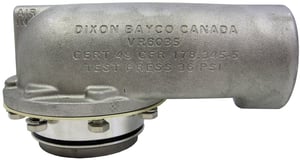 Sequential vapor vent-TTMA flange (part number VR6035SQ)
Emergency Valves
Sequential vapor vent-TTMA flange (part number VR6035SQ)
Emergency Valves
The emergency valve (sometimes called a foot valve) controls the entry and exit of petroleum from the tanker compartment. Located at the bottom of each compartment, the emergency valve is connected to the API valve by piping and can be either mechanically or pneumatically operated. The emergency valve is designed to minimize turbulence and spray of petroleum and therefore reduce the possibility of generating static electricity.
The emergency valve remains shut and prevents compartment discharge should a vehicular collision occur. For example, if an automobile collides with the tank truck undercarriage, the emergency valve will automatically close or remain shut, preventing the product in the compartment from escaping. A shear groove on the exterior of the emergency valve is designed to break away along with the piping leading to the API valve. However, the main poppet (valve) is designed to remain closed and intact on the inside of the compartment. The danger of product discharge is therefore limited to the short length of plumbing between the shear section and the API. The breakaway design prevents the compartment contents from being discharged and causing a more dangerous situation.
Typical pneumatic emergency valve
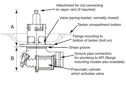 A. In an emergency, this section with a closed valve inside the compartment remains with the tanker.
B. In an emergency, this section (outside the compartment) is designed to break away at the shear groove, along with the piping to the API valve.
The trend is to pneumatically operate emergency valves. However, mechanically activated emergency valves (controlled by cable-operated levers) are still in use. Mechanical emergency valves often control vapor vents via a metal rod connected to both. The emergency valve and vapor vent operate simultaneously. Both items are opened during the loading and unloading process. Both remain closed at all other times.
Air interlock valves are simple, plunger-activated air valves that are linked to the truck airline system and used to direct pressurized air to activate other pneumatic devices on the tanker. There are many variations of air-activated systems used by transporters. Emergency valves, vapor vents, and trailer air brakes are commonly controlled devices. Air interlocks are often mounted on API valves, vapor valves, and safety bars and can be activated by coupling of hose, or terminal dry breaks, or by operating the safety bar. Air interlocks allow for improved safety, reduced operator error, and improved automation when loading and unloading petroleum. Several air interlocks are often found on petroleum trailers.
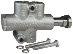 Standard air interlock model (part number 5000AIHD)
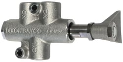 Air interlock with valve paddle plunger (part number 5000AIVHD)
API Valves
Air interlock with valve paddle plunger (part number 5000AIVHD)
API Valves
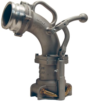
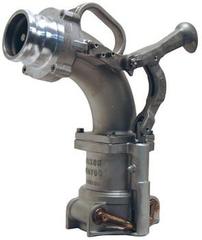
There are two basic styles of API valves: those that can be opened with a handle and those with no handle. By far the most popular product is the handle model; it allows for both loading and unloading of the tanker through this common valve.
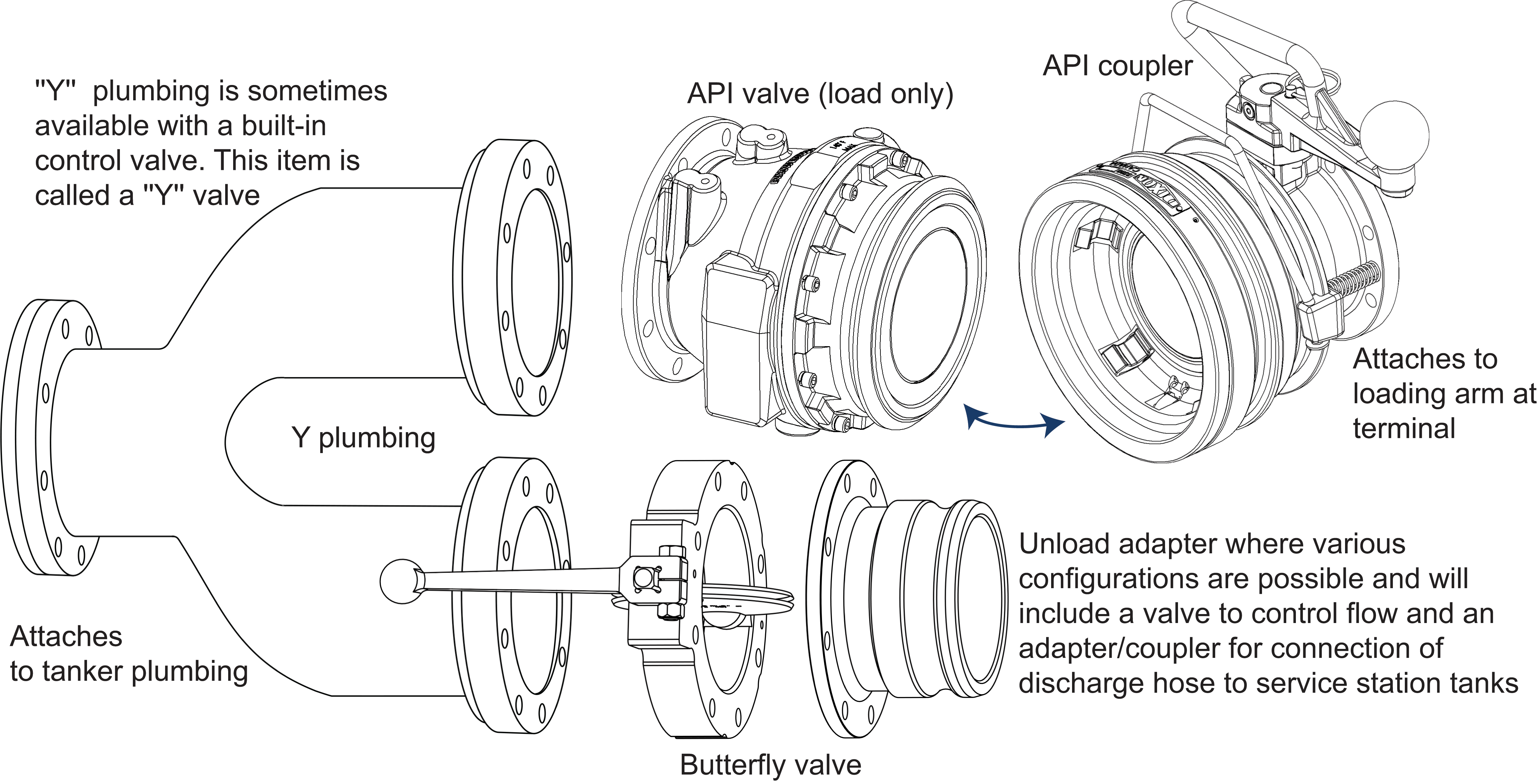
Both API models are spring-loaded, 4" poppet valves, which at the terminal mate with a specially designed API dry break coupling. The nose/coupler geometry of the API valve is made to a specific standard (API recommended practice API RP1004: 2003). The two items, the API valve (on the tank truck) and the API coupler (at the terminal) are designed for the fast, easy, and drip-free connection and transfer of gasoline from the terminal to the road tank truck.
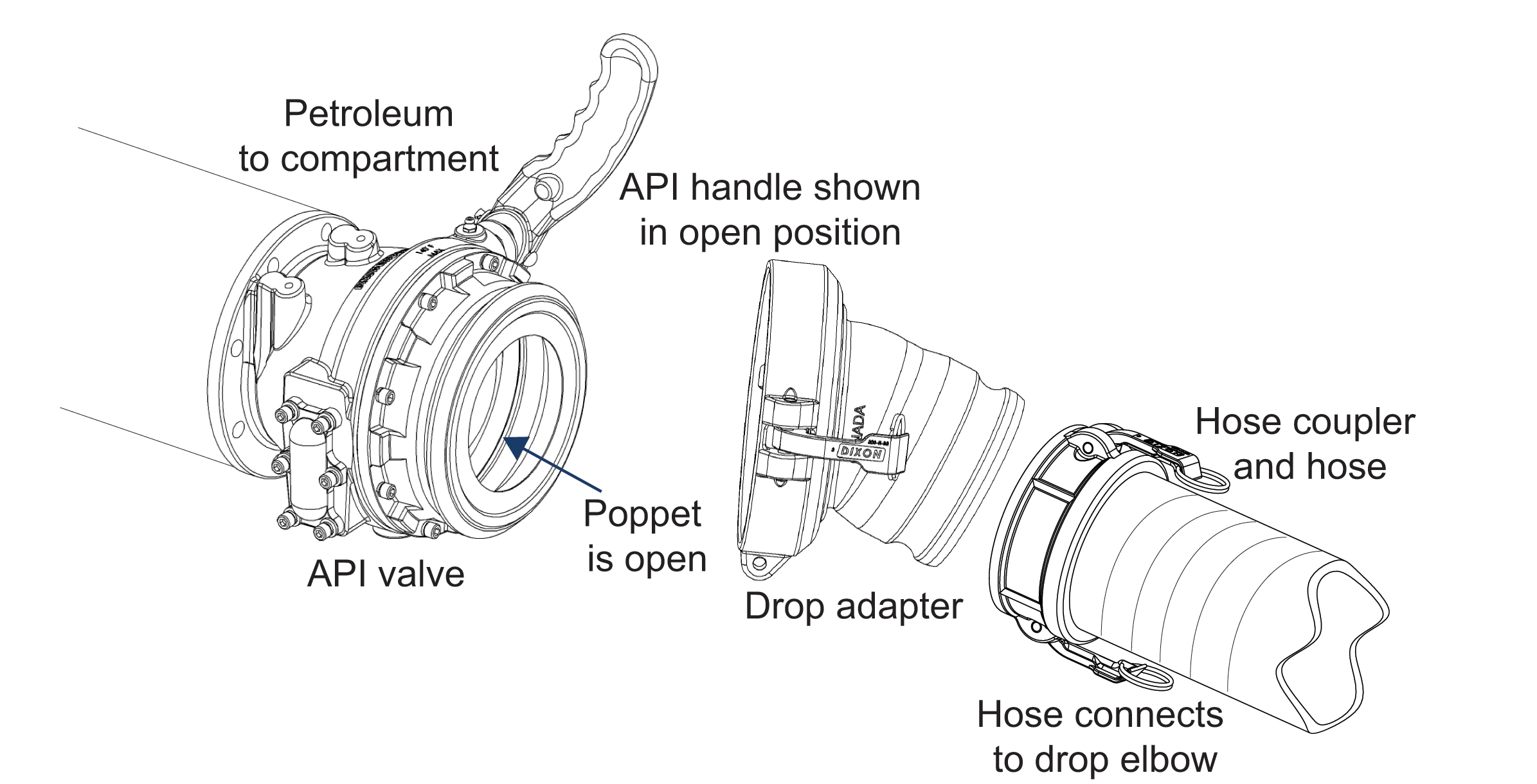
At the service station, a drop hose is connected to the handle model API valve. The other hose end is connected to the drop elbow and the underground tank pipe. Gasoline is gravity transferred from the tank truck to the underground tank when the API valve is opened by use of its handle.
Load-only APIs (no handle) are not utilized during service station drops. Flow is controlled by a separate Y valve or Y plumbing with a faucet or butterfly valve. Older style manifold systems can also employ load-only API valves.
Gravity Drop Adapters
Drop adapters are part of the service station unloading system when using API valves that are opened manually. Gravity drop adapters are simple couplers designed to attach and lock onto the API nose geometry on one end and allow attachment to a standard cam and groove hose couplings at the other end. They permit the drop hose, which uses standard cam and groove hose couplers, to link the API valve to the drop elbow and the underground tank.
Drop adapters are sometimes stored in the tool compartment of the tank truck until required during unloading at the service station. In some cases, they are left on the API and removed only when loading at the terminal. Gravity drop adapters typically come in two sizes for use with either 3" or 4" hose.
Drop Hose
The drop hose is used to transport gasoline between the tank truck and the underground tank during unloading at the service station. Standard cam and groove aluminum hose couplings are used on each end. Using a 4" diameter hose provides fast unloading; however, a 3" diameter hose is common because of reduced weight and cost.
Drop Elbows
Drop elbows are typically carried on the tanker and connect the underground tank collar to the drop hose. Elbows are used extensively throughout North America, Mexico, and parts of South America. They are not common in Europe and Asia. Elbows protect drop hose from damage due to kinking. They also make the hose connection to the underground tank more convenient. It should be noted that drop elbows are designed for use with a special underground tank collar.
By far the most common elbows are for 4" top seal collars. Most service stations have standardized on 4" fill piping.
Underground Tank Collars
The style and size of tank coupling will vary depending upon the country and whether vapor recovery is being used.
In North America, stations are usually equipped to use 4" drop elbows, which attach to 4" top seal couplings (some stations have 3" piping). In some locations 4" side seal elbows and couplings are employed. Elsewhere in the world standard cam and groove hose fittings are common in addition to special regional designs.
Service stations equipped with vapor recovery have a second outlet on the underground tank to allow vapor to escape and be transferred to the tanker during the unloading cycle. These outlets use a standard 4" quick coupler adapter but with a built-in, spring-loaded poppet (valve).
Where vapor elbows are employed, the elbow contains a bottom probe, which opens the valve when coupled to the collar. The adapter profiles for 4" top seal fill and vapor couplings are different to prevent drop elbows from attaching onto vapor collars and vapor elbows from attaching to fill collars.
Vapor Elbows
Vapor elbows are similar in design to drop elbows and function to make the vapor hose connection convenient for operators and to the hose from splitting due to kinks. When mounting, a probe on the bottom end automatically opens the poppet on the vapor collar, allowing vapors from the underground tank to escape. The vapor hose connects to the 3" adapter outlet on the elbow.
Vapor elbows are typically designed with 3" diameter bodies and with a 3" male adapter outlet. However, note that vapor service station piping and vapor collars are 4".
For stations that do not have a separate vapor outlet, a special co-axial elbow can be used. This elbow (part number 6400X) allows for both the drop of gasoline and the escape of fumes through a standard 4" top seal drop collar. A tube-within-a-tube design allows fuel to be dropped through the inside tube, while vapors escape around the outside. This is called a "single-point delivery system", compared to the two-point system, which has separate dedicated vapor and drop fittings. Two-point systems are preferred due to faster delivery drop-off.
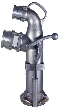
 Dual-point vapor recovery elbow (part number VR6200ANP)
 Heavy-duty dual-point vapor recovery elbow (part number VR6500)
 Single point coaxial drop elbow (part number 6400X)
Vapor Hose and Fittings
The vapor hose is typically 3" diameter (4" common at terminals). For connection to the vapor elbow, the hose can be equipped with a standard 3" shanked quick coupler. However, should the Dixon VR6200 vapor elbow be employed (with exit poppet) then the VR3000AL (with probe) is required. The probe is needed to open the exit end poppet on this vapor elbow model.
At the tank truck end, a special 4" x 3" probed hose coupler is needed. The coupler connects to the vapor valve on the tank truck. The coupler probe is required to open the poppet in the vapor valve.
The 4" vapor valve allows entry of displaced gasoline fumes from the underground tank to the 4" vapor piping system on the road tanker. The vapor hose coupler probe automatically depresses (opens) the poppet in the vapor valve when coupled.
Dixon provides two models: part number VR4000 with flange bulb design, sight glass, and drain plug and our standard model part number VR4100. The flange bulb design provides low resistance to vapor flow for fast loading of tank truck compartments at terminals. However, the VR4100 is more popular in the industry.
We hope you enjoyed reading this post and take a moment to share it with your colleagues. To learn more, contact a Dixon specialist or visit our Transportation market page.
This blog was excerpted from our Petroleum Tank Truck Industry Bottom-Loading and Vapor Recovery whitepaper.